Difference: Tutorial5thTCADDay3 (2 vs. 3)
Revision 32020-05-21 - AtlasjSilicon
3日目(デバイスシミュレーション)前回のSimple2Dの例題を走らせてみる。まずは、Simple2Dのプロジェクトを開いてください。 | ||||||||
| Added: | ||||||||
| > > | ||||||||
cd ~/work/Silicon/TCAD/Sentaurus/tutorials/Simple2D
swb . &
node 27だけ実行してあったと思います。 その構造に相当するIVシミュレーション(node 45)も実行して前回同様、Inspectorを使ってIV_n45_des.plt を開いてみてください。 | ||||||||
| Changed: | ||||||||
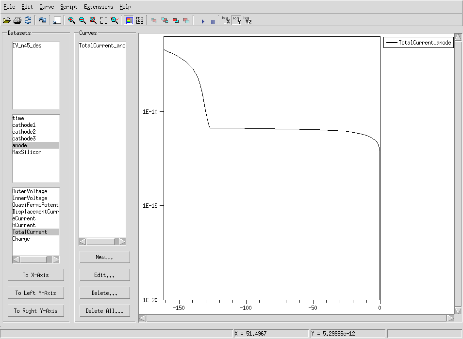
| < < | anodeの OuterVoltage をx軸に、anodeのTotalCurrentをy軸に指定してプロットを描くとしたの図のようになります。 | |||||||
| > > | anodeの OuterVoltage をx軸に、anodeのTotalCurrentをy軸に指定してプロットを描くとしたの図(左)のようになります。 | |||||||
| Deleted: | ||||||||
| < < |  | |||||||
| 最初の例題で見たグラフとずいぶん違う形になっていますが、これは130V付近で電場の集中による雪崩増幅が起こったことを示唆しています。 一般的に、p-n 接合に大きな逆方向電圧がかけられると,接合は降伏現象(Break down)を起こし,大電流が流れます。 Y軸をログスケールにするともう少しわかりやすいかもしれません。上の方真ん中付近にある logYというボタンを押してみてください。 | ||||||||
| Changed: | ||||||||
| < < |  | |||||||
| > > | 下の図(右)のようになります。(対数グラフになっているので縦軸は絶対値になっているので注意! (0,0)は右下です。) | |||||||
| Added: | ||||||||
| > > |   | |||||||
| 130V付近までは依然見た様な電流電圧特性を示しますが、その後急に増えていることがわかります。 この降伏(Break down)が起こる電圧をBreak down voltageと呼びます。 Breakを起こしたときの電場分布と電子の密度分布を見てみましょう。 | ||||||||
| Added: | ||||||||
| > > | node 45で右クリック、 svisual で n45_des.tdrを開く。
(scaling : X to Y ratioを10くらいにして表面領域を拡大してみてください。)
電場分布 (Electric Field)や、電子密度(Electron Density)、衝突イオン化(Impact Ionization)などを見てみるとガードリングの付近で非常に電場が集中していることがわかります。
一般的に電子の持つ運動エネルギーがシリコンのバンドギャップを超えたとき、雪崩増幅が起こる。この電圧はシリコンであれば約300kV/cm以上である。(出典: SM.Sze. 『Semiconductor Device』3.7章「高電界効果」より)
電場分布をy軸に沿った軸でカットしてみると3e5V/cmを超えていることがわかります。

Simple2D のIVシミュレーションのコマンドIV_des.cmdという名前のファイルを見てみましょう。以下のコンポーネントからできています。File {...}
Electrode {...}
Physics {...}
CurrentPlot {...}
Solve {...}
Plot {...}
File sectionまず初めに入力ファイルや出力ファイルを指定する。 入力ファイルは Gridとparameter。 Gridでは sdeで作った構造体を読み込みます。Work Benchでdevice simulationを行おうとしているnodeの左にあるSimple2Dというsdeを実行したノードの番号は @node|Simple2D@で取得できます。 parameterはシミュレーションに使う細かいパラメータを設定しています。通常はsdevice.parというファイルが使われます。 出力ファイルはCurrentとPlot が結果になります。 outputでlogを出力します。 Current はすべてのシミュレーション(下のSolveで指定)の電気的な結果の値が詰まったファイルを出力します。 @plotFile {
Grid = "n@node|Simple2D@_msh.tdr"
Current = "@plot@"
Plot = "@tdrdat@"
output = "@log@"
parameter = "@parameter@"
}
Electrode sectionここでは「電極」を指定します。IVなどのシミュレーションをする際にどこをGNDにどこを電位Vにするなどを指定する必要があります。 ただし、構造体をsdeで作った際に電極になる場所を作っておく必要があります。前回の sdegeo:define-contact-set を参照。 Simple2D_des.cmdのなかでストリップ電極数(cathode1,2,3)+裏面(anode)の4つの電極を作って、それぞれを 0.0 Vに設定します。
Electrode {
        !(
        for {set i 1} {$i<=@NumStripes@} {incr i} {
                                        puts "\{name = \"cathode${i}\"   voltage = 0.0   eRecVelocity=1e7 hRecVelocity=1e7 \}"
        }
        )!
        {name = "anode"   voltage = 0.0         eRecVelocity=1e7 hRecVelocity=1e7 }

}
Physics sectionPhysics { ##AreaFactor=1e8 ##Fermi } Physics (material="Silicon") { Mobility( DopingDep (Unibo) HighFieldsat (GradQuasiFermi) ) Recombination( SRH(DopingDep TempDep) Auger ##hAvalanche(UniBo) eAvalanche(UniBo) hAvalanche eAvalanche ) EffectiveIntrinsicDensity (OldSlotboom) Traps( ( name="state1" acceptor conc=@<fluence*1.613>@ Level FromConductionBand EnergyMid =0.42 eXsection=2E-15 hXsection=2E-14 ##eJfactor=1.0 hJfactor=1.0 ) ( name="state2" acceptor conc=@<fluence*100.0>@ Level FromConductionBand EnergyMid =0.46 eXsection=5E-15 hXsection=5E-14 ##eJfactor=1.0 hJfactor=1.0 ) ( name="state3" donor conc=@<fluence*0.9>@ Level FromValenceBand EnergyMid =0.36 eXsection=2.5E-14 hXsection=2.5E-15 ##eJfactor=1.0 hJfactor=1.0 ) ) } CurrentPlot sectionCurrentPlot { eLifeTime(Maximum(material="Silicon")) hLifeTime(Maximum(material="Silicon")) eAvalanche(Maximum(material="Silicon")) hAvalanche(Maximum(material="Silicon")) } Math sectionMath { ##CDensityMin=1e-100 Extrapolate Derivatives Avalderivatives Digits=5 Notdamped=1000 Iterations=20 RelerrControl ErrRef (electron)=1e6 ErrRef (hole)=1e6 RhsMin =1e-15 eMobilityAveraging=ElementEdge hMobilityAveraging=ElementEdge ParallelToInterfaceInBoundaryLayer (-ExternalBoundary) ##Method=Blocked ##SubMethod=ILS (set=1) ##Method=ILS (set=1) Method=Pardiso ILSrc = " set(1) { iterative( gmres(100), tolrel=1e-8, tolunprec=1e-4, tolabs=0, maxit=200 ); preconditioning( ilut(0.0001,-1), left ); ordering( symmetric=nd, nonsymmetric=mpsilst ); options( compact=yes, verbose=0, refineresidual=0 ); }; " number_of_threads=4 } Solve SectionSolve { Poisson plugin { Poisson Electron Hole } Coupled { Poisson Electron Hole } NewCurrent ="IV_" Quasistationary ( DoZero MaxStep =1 MinStep =1e-8 InitialStep =1e-5 Increment=1.6 Decrement=4.0 Goal { Name="anode" Voltage=-120} BreakCriteria {Current (Contact = "anode" minval = -1e-7 )} ) { Coupled { Poisson Electron Hole } } Quasistationary ( DoZero MaxStep =1 MinStep =1e-8 InitialStep =1e-5 Increment=1.6 Decrement=4.0 Goal { Name="anode" Voltage=@Vop@} BreakCriteria {Current (Contact = "anode" minval = -1e-7 )} ) { Coupled { Poisson Electron Hole } } system("") } Plot SectionPlot { Current/Vector eCurrent/Vector hCurrent/Vector eDensity hDensity ElectricField /Vector Potential CurrentPotential DopingConcentration eMobility hMobility DonorConcentration AcceptorConcentration AvalancheGeneration eAvalanche hAvalanche eLifeTime hLifeTime } | |||||||
--
| ||||||||
| Added: | ||||||||
| > > |
| |||||||
View topic | History: r14 < r13 < r12 < r11 | More topic actions...
Ideas, requests, problems regarding TWiki? Send feedback