/2ndtcadws1.png)
IVsimulation
sdeviceの構造
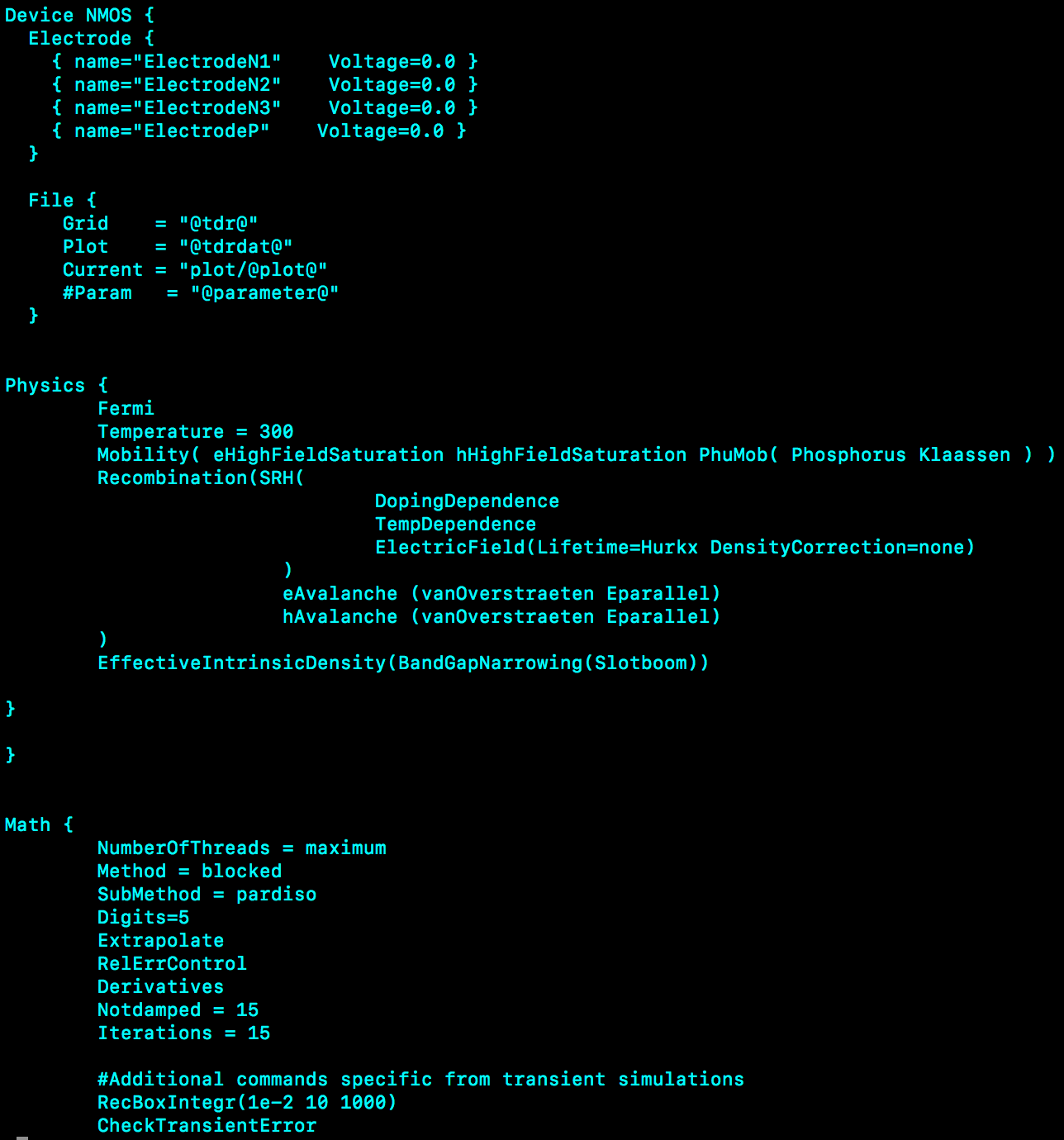
sdeviceファイルは以下のような構造からなる. Electronode 電極の設定。sdeで作成した電極名を指定しどの場所でシミュレーションを行うかを指定する。 File 読み込むファイル、及び今回のアウトプットするファイルの指定。 読み込むファイルは拡張子.tdr。 Physics 今回の物理的なシミュレーションの指定。 ドリフト拡散輸送モデルを使用。このphysics全体がドリフト拡散輸送モデルの形になっている。 温度/MI粒子/放射線損傷/どのような統計に従うかなど。 Math シミュレーションするときの条件設定。 Plot シミュレーションの結果をsvisal上で表示するものの指定。 Solve 解析手法の設定。 シミュレーションの電圧のステップなどを指定できる。動かし方
/<div class="igp"><a name="igp1"></a><div class="igpThumbNails"><table class="igpThumbNailsTable"><tr>
<td width="25%" class="igpThumbNail"><a href="http://atlaspc5.kek.jp/do/view/Main/IVsimulation%282ndWS%29?id=1&filename=124731246312522125401253112471125191248312488_2018-08-29_0.18.20.png#igp1"><img src="/pub/images/Main/IVsimulation(2ndWS)/1/thumb_124731246312522125401253112471125191248312488_2018-08-29_0.18.20.png" title="124731246312522125401253112471125191248312488_2018-08-29_0.18.20" alt="124731246312522125401253112471125191248312488_2018-08-29_0.18.20.png"/></a></td>
<td width="25%" class="igpThumbNail"><a href="http://atlaspc5.kek.jp/do/view/Main/IVsimulation%282ndWS%29?id=1&filename=2ndtcadws1.png#igp1"><img src="/pub/images/Main/IVsimulation(2ndWS)/1/thumb_2ndtcadws1.png" title="2ndtcadws1" alt="2ndtcadws1.png"/></a></td>
<td width="25%" class="igpThumbNail"><a href="http://atlaspc5.kek.jp/do/view/Main/IVsimulation%282ndWS%29?id=1&filename=_2018-08-29_0.18.20.png#igp1"><img src="/pub/images/Main/IVsimulation(2ndWS)/1/thumb__2018-08-29_0.18.20.png" title="_2018-08-29_0.18.20" alt="_2018-08-29_0.18.20.png"/></a></td>
<td> </td>
</tr>
<tr><td class="igpThumbNailTitle">124731246312522125401253112471125191248312488_2018-08-29_0.18.20 </td>
<td class="igpThumbNailTitle">2ndtcadws1 </td>
<td class="igpThumbNailTitle">_2018-08-29_0.18.20 </td>
<td> </td></tr>
</table></div>
</div>
There are 3 images in this page) Project>New>New Projectから新しいプロジェクトを作り、 Save asで保存する。(ファイル名はIVなど)
sde_dvs.cmdを作ったディレクトリにコピーする。
sdevice_des.cmdを作成。(/home/dharada/work/Sentaurus/Silicon/TCAD/2ndworkshop/IV/sdevice_des.cmdからコピー)
No toolを右クリックしてAddを押し、sdeとsdeviceを加える。
sdeviceの一つ下のセルでAdd Parameterをし変数にパラメータを与える。Parameter に変数名、List of valueにパラメータを入力。
今回はVop(バイアス電圧)のみで-50Vくらいでいいと思います。
右上の走ってるマークをクリックしlimitedモードで走らせる。
シミュレーションが終わるとセルが黄色に変わる。
セルをクリックした状態で右上の目のマークからInspect(select File)をクリックする。
ElectrodePを選択し、x軸をOuter Voltage,y軸をTotal CurrentにするとIV曲線が見えるはず。
Project>New>New Projectから新しいプロジェクトを作り、 Save asで保存する。(ファイル名はIVなど)
sde_dvs.cmdを作ったディレクトリにコピーする。
sdevice_des.cmdを作成。(/home/dharada/work/Sentaurus/Silicon/TCAD/2ndworkshop/IV/sdevice_des.cmdからコピー)
No toolを右クリックしてAddを押し、sdeとsdeviceを加える。
sdeviceの一つ下のセルでAdd Parameterをし変数にパラメータを与える。Parameter に変数名、List of valueにパラメータを入力。
今回はVop(バイアス電圧)のみで-50Vくらいでいいと思います。
右上の走ってるマークをクリックしlimitedモードで走らせる。
シミュレーションが終わるとセルが黄色に変わる。
セルをクリックした状態で右上の目のマークからInspect(select File)をクリックする。
ElectrodePを選択し、x軸をOuter Voltage,y軸をTotal CurrentにするとIV曲線が見えるはず。Comments
There are 3 images in this page


| I | Attachment | History | Action | Size | Date | Who | Comment |
|---|---|---|---|---|---|---|---|
| |
2ndtcadws1.png | r1 | manage | 172.6 K | 2018-08-28 - 16:44 | AtlasjSilicon |
Topic revision: r2 - 2018-08-28 - AtlasjSilicon

Ideas, requests, problems regarding TWiki? Send feedback