Difference: FE65p2ChipDAQ (8 vs. 9)
Revision 92016-08-23 - KojiNakamura
DAQ development for FE65-P2 chipIntroduction | |||||||||||||||||||||||||||||||||||||||||||||||||
| Changed: | |||||||||||||||||||||||||||||||||||||||||||||||||
| < < | FE65-P2 is the readout ASIC with 65nm processing as pre-pre-production for the RD53A /B chips used by HL-LHC ITK pixel upgrade. | ||||||||||||||||||||||||||||||||||||||||||||||||
| > > | FE65-P2 is the readout ASIC with 65nm processing as pre-pre-production for the RD53A/B chips used by HL-LHC ITK pixel upgrade. | ||||||||||||||||||||||||||||||||||||||||||||||||
|
more information is available in :
motivation talk in AUW April 2016 | |||||||||||||||||||||||||||||||||||||||||||||||||
| Changed: | |||||||||||||||||||||||||||||||||||||||||||||||||
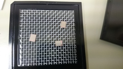
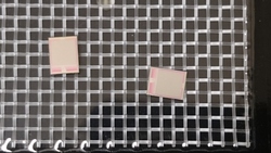
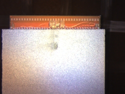
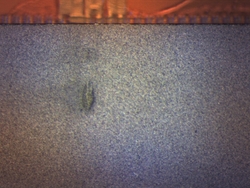
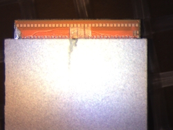
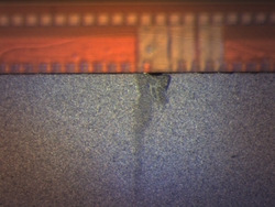
| < < | Bump Bonding at SLAC | ||||||||||||||||||||||||||||||||||||||||||||||||
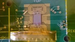
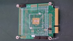
| > > | Chips and Bump Bonding at SLAC | ||||||||||||||||||||||||||||||||||||||||||||||||
| Added: | |||||||||||||||||||||||||||||||||||||||||||||||||
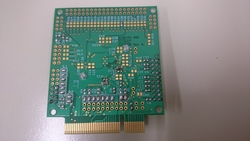
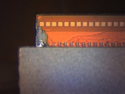
| > > | KEKFE1 KEKFE2 KEKFE3 KEKFE4 KEKFE5 KEKFE6 | ||||||||||||||||||||||||||||||||||||||||||||||||
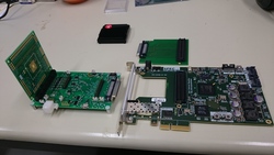
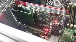
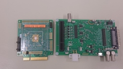
DAQ development by SPEC
| |||||||||||||||||||||||||||||||||||||||||||||||||
| Changed: | |||||||||||||||||||||||||||||||||||||||||||||||||
| < < | How to setup SPEC board | ||||||||||||||||||||||||||||||||||||||||||||||||
| > > | How to setup SPEC board | ||||||||||||||||||||||||||||||||||||||||||||||||
mkdir -p /home/atlasj/work/SPEC/YARR
cd /home/atlasj/work/SPEC/YARR/
git clone https://github.com/Yarr/Yarr.git
git fetch
git checkout fe65_p2
cd /home/atlasj/work/SPEC/YARR/Yarr/src/kernel
make
sudo make install
sudo depmod
cd ../ ; make
sudo modprobe specDriver bin/programFpga ../hdl/syn/yarr_fe65p2_revB.bit bin/test bin/benchmarkDma | |||||||||||||||||||||||||||||||||||||||||||||||||
| Added: | |||||||||||||||||||||||||||||||||||||||||||||||||
| > > | How to configure chips and run scanGeneral scan consolHitOr self trigger scan1. Run digital scan2. Run analog scan 3. Prepare config: - Enable all pixels: # bin/config_fe65-p2 fe65p2.json (Overwrites config file) - Apply digital scan mask: # bin/applyMask fe65p2_ch0_digitalscan_EnMask.dat fe65p2.json - Copy masked config: # cp masked_fe65p2.json fe65p2.json - Apply analog scan mask: # bin/applyMask fe65p2_ch0_analogscan_EnMask.dat fe65p2.json - Copy masked config: # cp masked_fe65p2.json fe65p2.json 4. Run noise scan (~5min) 5. Apply noise mask: - Apply digital scan mask: # bin/applyMask fe65p2_ch0_noisescan_NoiseMask.dat fe65p2.json - Copy masked config: # cp masked_fe65p2.json fe65p2.json 6. Mask stuck/noise hitter pixels: - #bin/fixHitbus fe65p2.json (takes quite some time ~15min) - Only pixels which will get masked get printed to stdout, optimally these should not be many - If many pixels appear to not work something is wrong - You can observe the process by probing HitOr Output and Trigger, there should be two hitOr pulses per trigger - The program produces a mask hitbus_enMask.png - Copy masked config: # cp masked_fe65p2.json fe65p2.json 7. Run exttrigger scan: - If everything went right you should observe a trigger rate of a few Hz without a particle source - With source the rate should be much higher - The internal dead time is 200bc (currently hardcoded for testing) | ||||||||||||||||||||||||||||||||||||||||||||||||
ImagesThere are 24 images in this page --
| |||||||||||||||||||||||||||||||||||||||||||||||||
View topic | History: r30 < r29 < r28 < r27 | More topic actions...
Ideas, requests, problems regarding TWiki? Send feedback
